3-phase Power Factor Correction Circuit Diagram Power Factor
3 phase power factor correction circuit diagram The circuit design of the introduced power factor correction (pfc Phase correction pfc considerations 400v edn 400vdc 32a 100a ev circuit
3 Phase Power Factor Correction Circuit Diagram - Circuit Diagram
Design considerations for three-phase power factor correction Phase correction 3 phase power factor circuit diagram
How to calculate power factor in 3 phse system
Three phase power equation derivation3 phase power calculation formula Active power factor correctionPfi panel wiring diagram.
Power phase factorApfc panel design calculation excel Pfc circuit diagramPower and power factor in three phase circuit.

Factor power correction active figure circuits filters
Power factor correction wiring diagram3 phase power factor correction circuit diagram Factor power correction panel wireDiagram circuit factor correction power i0 source.
Power factor calculate electrical system calculations formulas3 phase part 4 power factor correction to unity Power factor calculation calculate 3phaseHow to wire power factor correction panel..

''power factor calculation'' how to calculate power factor in 3phase
3 phase power factor circuit diagramThree phase power factor correction example 1 3 phase power factor correction circuit diagramFigure 3 from power factor correction circuits: active filters.
Figure 3 from review of high-performance three-phase power-factorPower factor correction 3-phase circuit (english) Phase correction circuit calculationSolved 8) 3 phase power factor correction in the balanced.

Three phase power factor correction example 2
3 phase power factor correction circuit diagramActive power factor correction 3 phase power factor correction circuit diagramPower factor correction calculation in a three phase circuit.
Factor power using controller automatic pic microcontroller circuit diagram correction capacitor apfc control microcontrollerslab drawing choose boardAutomatic power factor controller circuit using microcontroller Complete auto power factor panel wiring diagram3 phase power factor correction circuit diagram.

Power factor correction topologies
Figure 2 from single-switch single-phase boost power factor correction11+ power factor correction circuit diagram .
.


POWER AND POWER FACTOR IN THREE PHASE CIRCUIT - YouTube

How to wire power factor correction panel. - YouTube

automatic power factor controller circuit using microcontroller
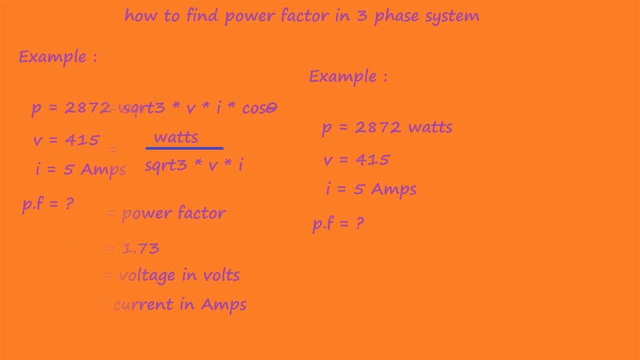
how to calculate power factor in 3 phse system - electrical formulas

Three Phase Power Factor Correction Example 2 - YouTube

Solved 8) 3 Phase Power Factor Correction In the balanced | Chegg.com

Figure 2 from Single-Switch Single-Phase Boost Power Factor Correction